Requirements of the physical setup
This document describes the physical setup and challenges for utilizing tag-grid-scanner in real-world applications.
Tags
- Rectangular: The detector can detect rectangular tags. The most common use case is square tags.
- Equal size: All tags have the same size.
- Rotation symmetry: When designing the tag codes, take into account the rotation symmetry. Tags that are rotations of each other are considered the same tag.
- High contrast: The detector works on grayscale images. Hence, only the colors black and white should be used. Other colors may work as well as long as there is still enough contrast between them when converted to grayscale.
- Matted surfaces: Glossy surface cause reflections. A black but glossy surface can appear whitish to the camera when it acts as mirror to a light source. Glossy tags may not pose a problem if the lights and the camera positioned to avoid reflections. Otherwise, aim for matted tag surfaces.
Grid
The tags need to be aligned in a uniform grid, usually on a transparent surface, such that the camera can view the tag grid from below:
- Rectangular, equidistant, uniform: All rows have the same number of tags. All columns have the same number of tags. The spacing between tags always the same (see Gaps). All tags have the same size.
- Transparent: The camera needs to be able to see the tags. If you choose to use an infrared camera and infrared lighting, you may get away with a surface that is opaque to visible light, but this is untested.
- Gaps: It is possible to add gaps between the tags. This usually makes it easier to insert and remove tags from the grid. Note that additional light might shine through the gaps and glare into the camera. Therefore, the gaps should either be kept small or covered by an opaque material.
Illuminating the tag grid
- Uniform lighting: Try to achieve similar lighting conditions for all tags, at least when viewed from the camera position.
- Noise reduction: If the lighting is not strong enough, the camera image will contain a lot of noise that can drastically reduce detection quality. It may also cause detection results to vary from one frame to the next, even though the tags did not change.
- Glare: The light sources must not be visible to the camera. Add a lens hood if necessary. Consider that reflections of light sources off glossy surfaces (such as the transparent board holding the tags) may cause glare issues are well.
Camera choice
Choosing the right camera is important for the best detection results:
- Wide angle lens: If you plan to place the camera below the tag grid, the camera probably needs a somewhat wide angle lens to capture the whole grid from a short distance. You might get away with a longer focal length if the grid and tag sizes are small or you capture the grid via a mirror, but care has to be taken not to distort the image by the additional reflection (e.g. due to a mirror that’s not perfectly flat). If you use a zoom lens, it should be possible to lock it such that it does not change accidentally.
- Fixed or manual focus: Many lenses have different fields of view for different focus distances. Lens calibration and region of interest setting may also only be valid for a specific focus distance. Therefore, the lens should either be fixed focus or manual focus. Another possibility is to use a camera that allows locking the focus distance via a software setting.
- Wide dynamic range: If there are additional light sources visible from the camera’s location, e.g. directly or via reflections on glossy surfaces, the camera image might get overexposed in certain areas and this may detection issues when these bright spots are close to one of the tags. We have made good experience with cameras that support a wide dynamic range and, therefore, attenuate this issue automatically. Another option is to tweak the exposure time, if your camera supports that, but this may not be possible depending on the dynamic range of your scene.
- Lens distortion: Either choose a camera/lens that does not take any measures to correct lens distortion, or try to
choose a camera/lens combination that corrects distortion very well. Certain types of lens distortion can be corrected
by the
tag-grid-scannergiven proper calibration data. However, trying to correct distortion on an image that has been generated through in-camera distortion correction might not give satisfactory results.
We settled on the ELP 3MP WDR USB camera with 2.9mm lens (ELP USB3MP01H) and corrected lens distortion in software.
Camera placement
The positioning of the camera also affects the quality of the detection results.
- Position the camera as orthogonal as possible to the tag grid to avoid excessive keystone distortion.
- If something is projected onto the tag grid, the projection might shine through the grid (between the tags or if tags are removed) and glare into the camera lens. Depending on the brightness of the projection, this may result in overexposed areas in the camera image causing detection problems for adjacent tags.
Take both aspects into account and position the camera just outside the frustum created by the projector and the tag grid, but not too far away to keep keystone distortion low. Add a bit of margin to be on the safe side with respect to overexposure issues.
Camera mount
The camera mount needs to be very rigid. The camera should not move at all. Otherwise, re-calibration will be necessary.
Fiducial markers
The tag-grid-scanner can also detect fiducial markers, such as ArUco or AprilTag markers, that act as physical
reference points for the region of interest. These markers are tracked from one frame to the next to compensate for
camera movements after initial configuration. If all preconfigured markers are found in the distortion-corrected camera
image, a perspective coordinate transformation (homography) is derived from the matched markers. This transformation is
then used to map the originally configured region of interest into a valid region of interest with respect to the
current image. In many cases, this can compensate for small to medium camera movements caused by vibrations or thermal
expansion of the camera mount or furniture. It is highly recommended to include such fiducial markers in the physical
setup.
- The markers must be placed such that the polygon defined by the convex hull of all marker corners does not intersect the tag grid.
- The markers must be fully visible in the camera image after the lens distortion correction has been applied.
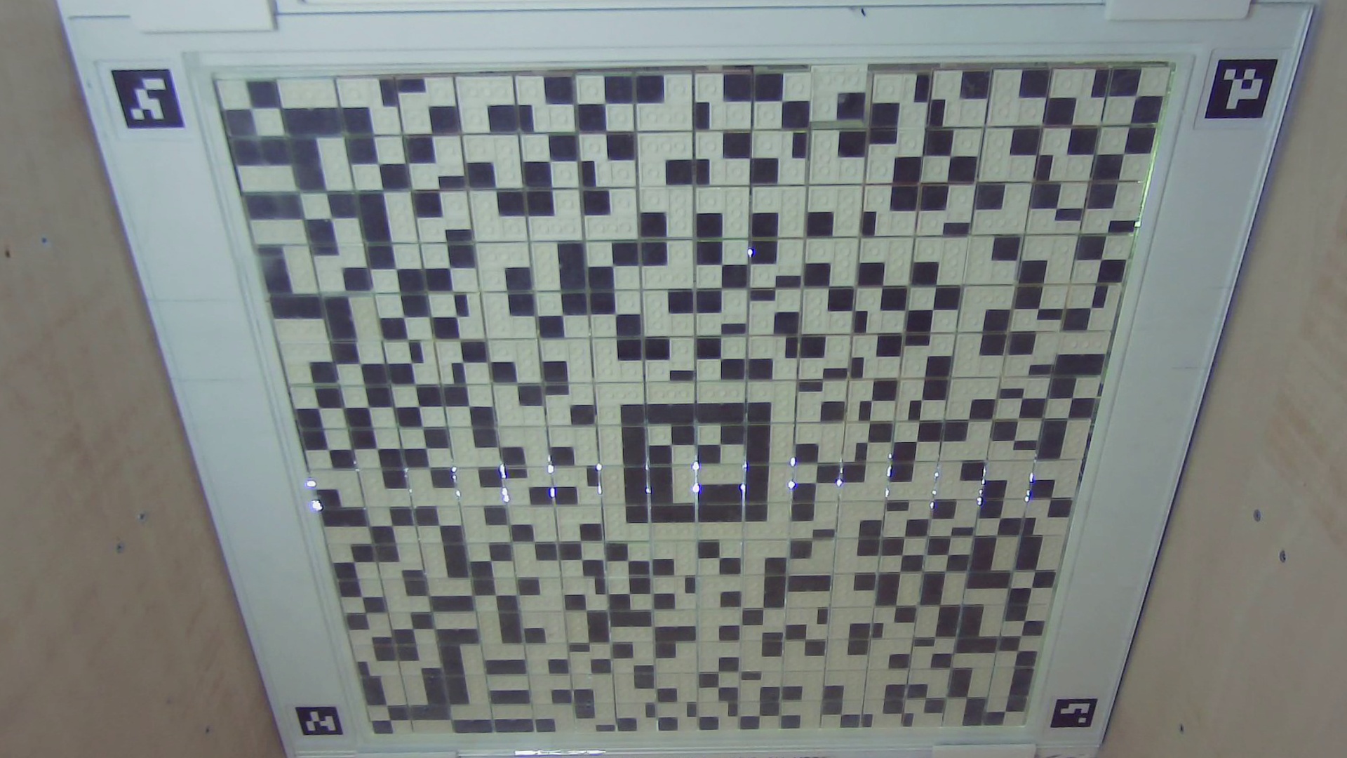
The final setup may look like this: